| |
|
Click an image to enlarge. |
On a typical car, a large front sway bar tends to increase understeer. However due to the McPhearson strut geometry on the Impreza platform, the understeer generally caused by a stiffer FSB is surpassed by the improved camber geometry that reduces understeer. As a result, I chose a large FSB (27mm) in comparison to my 24mm RSB (unlike many cars that benefit from a larger FSB).
This is a fairly straight forward installation, but it is more involved than the RSB because there are a few components blocking it that must be removed. Since my car is older, it took 3-4 hours but would probably take 2-3 hours on a newer car. Since I was removing these components, I went ahead and did the Steering Rack Bushing Upgrade at the same time. |
|
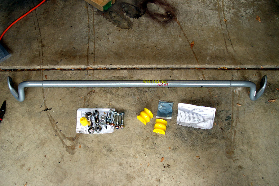
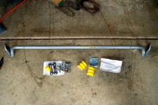
Here's what you need:
New Sway bar, bushings
and grease
New end links (optional)
Ratcheting wrench and array of sockets (12mm, 14mm, 16mm, 17mm) and extensions.
Array of open end wrenches (12mm, 14mm, ratcheting if possible)
5mm Hex/Allen wrench
PB Blaster or other penetrating lubricant
1" hose clamp and strip of rubber (optional, to prevent swaybar walk) |
|
 |
|
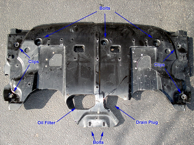
| The first item you need to get out of the way is the under tray. See my oil change DIY for info on removing the under tray. |
|
 |
|
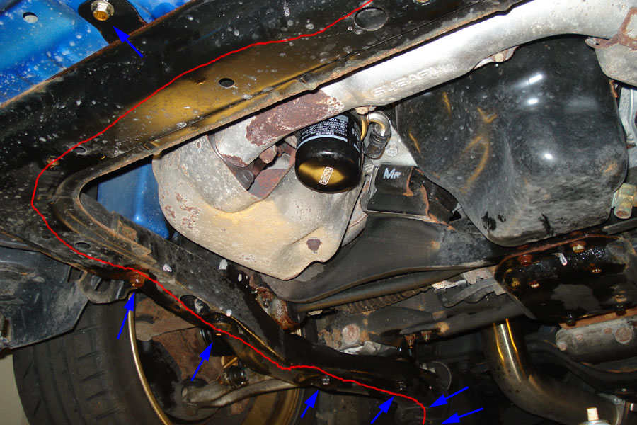
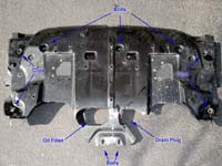
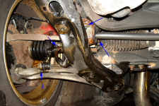
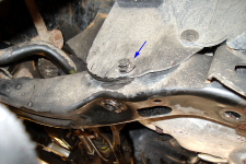
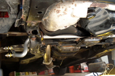
With the tray removed, you can see the all of the components.
The red arrows indicate the bolts to remove the jacking plate. The red line indicates the subframe that needs to be removed.
The blue arrows indicate the main components of the sway bar, notably the end links and the mounting brackets. |
|
 |
|
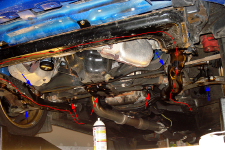
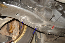
| Here is a closer look at the left (driver) side. The blue arrows point to the two mounting bracket bolts and the two end link bolts. As you can see the subframe is blocking these components which is why it should be removed. |
|
 |
|
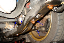
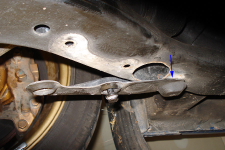
| Here is a closer look at the right (passenger) side. The blue arrows point to the two mounting bracket bolts and the two end link bolts. As you can see the subframe is blocking these components which is why it should be removed. |
|
 |
|
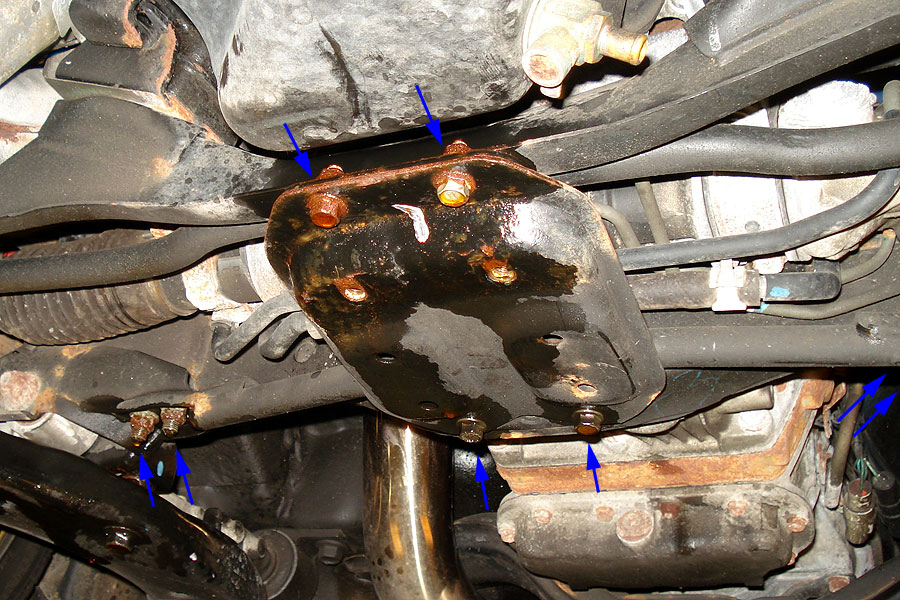
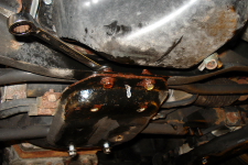
Here is a close up of the jacking plate which should also be removed. Note that the shape of the 04 STi plate is different than later models.
There are 8 bolts. The four bolts on the left and right side are 14mm and the 4 bolts on the center plate are 12mm.
|
|
 |
|
|
Remove the four 12mm bolts around the center plate first. Note that the two bolts on the front have free nuts on top that you'll need to use a wrench to hold otherwise the bolts will just spin.
When you remove these four, the central plate will come off. Put this to the side and remove the remaining four 14mm bolts for the other part.
|
|
 |
|
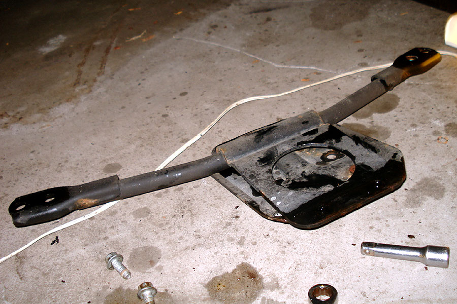
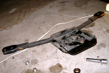
| Here you can see the two parts of the jacking plate removed. |
|
 |
|
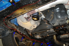
Next is the subframe. There are a total of 14 bolts (seven on each side).
I will refer to the bolts using numbers 1-7 with 1 starting at the front and 7 ending at the back. Handle both sides (left and right) the same way.
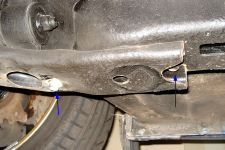
Here you can see bolt #1 in the top left corner. The remaining are seen along the bottom of the picture. #6 and 7 are just off the edge of the picture.
Loosen bolt 1 (12mm IIRC) but do not remove it until later. |
|
 |
|
There is also a plastic clip attaching the subframe to the wheel well covers that needs to be removed.
Remove the clips by pulling the center piece out with a flat headed screwdriver, then removing the entire clip. |
|
 |
|
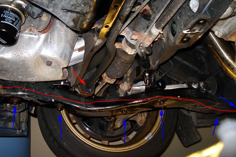
Here is a close up with blue arrows indicating bolts 2-6 (7 is off the edge).
The red arrow shows the sway bar mounting bracket.
Remove bolts 2-5 (17mm bolts). They are pretty long and a couple of them may be extremely corroded and will take some muscle. I got most of these off with a long ratching wrench but there were a couple that I needed to use a breaker bar. |
|
 |
|
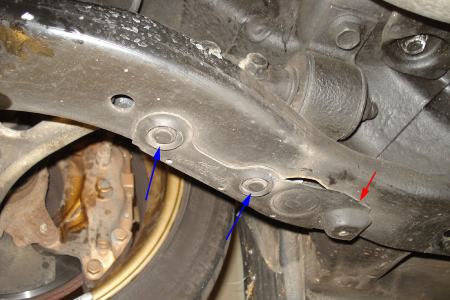
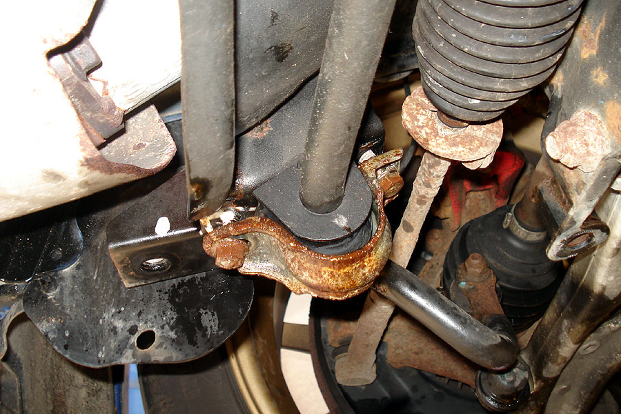
Bolt 6 (red arrow) is protected by a plastic shield, held on by 2 plastic clips (blue arrows) and a mounting tab (see next picture)
Remove the two clips. |
|
 |
|
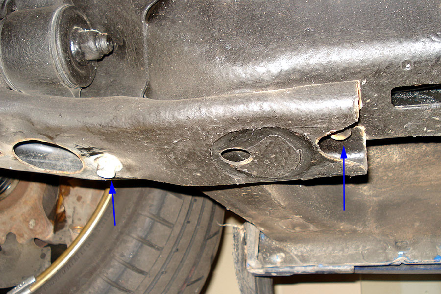
Once the clips are removed, slide the plastic shield back to release the mounting tab (behind the blue arrow).
|
|
 |
|
Now you can see bolt 6 (left arrow). Also in this picture is bolt 7 (right arrow).
Bolt 7 holds up the edge of the subframe but does not have an actual hole so once you've removed bolts 1-6, you can simply slide the subframe off of bolt 7.
Remove bolt 6 and loosen bolt 7 (14mm bolts). Bolt 1 is still be attached if you followed instructions. |
|
 |
|
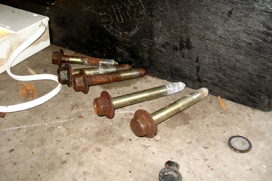
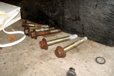
| Here are bolts 2-6 (right to left) along with the plastic clip for one side. Make sure to keep these in order as the lengths differ |
|
 |
|
To remove the subframe I positioned myself so that my chest was under the front of the subframe, then removed bolt 1 for both sides and lowered the subframe onto my chest. Then I reached back and pulled the subframe forward so it slipped off bolt 7.
Then, supporting the middle and back of the subframe with my arms and the front of the subframe with a leg, I continued to slide the subframe forward until it was free of the car (or you could get a friend to help). Sorry, forgot to take a pic of the subframe alone. |
|
|
|
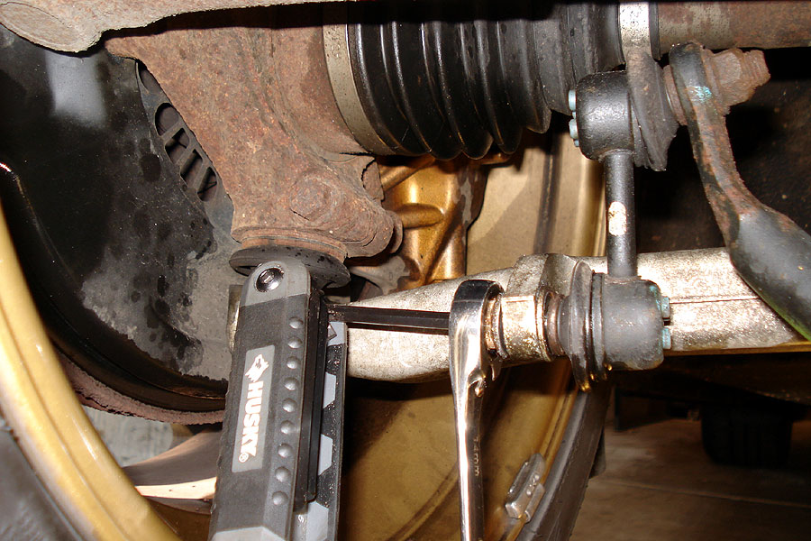
Now that all the parts in your way are gone, you can actually start on the sway bar. Since I'm replacing the end links, I just had to remove the bolt from the control arm. If only replacing the bar, you would only have to remove the bolt from the sway bar.
The front end link bolts have 5mm Hex holes in the end (unlike the rears which have cutouts on the collar for a wrench) so you need to use an allen wrench along with a 14mm open ended or ratcheting wrench to remove the nuts. |
|
 |
|
Next, remove the bolts for the bracket. Keep the bracket and the bolts as you will reuse them.
Since you removed the subframe and jacking plate, the sway bar will drop stright down, making it very easy to remove. |
|
 |
|
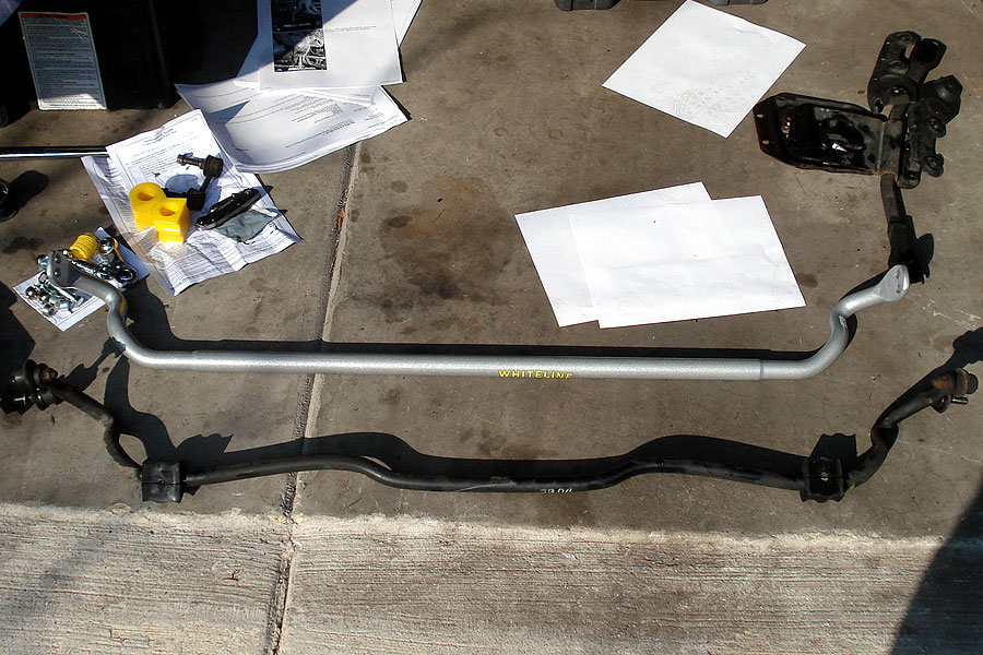
| Here is a comparison between the new Whiteline 27mm Adjustable Front Sway Bar and the stock bar. |
|
 |
|
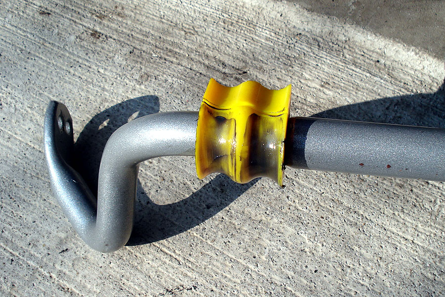
| Grease up the new bushings and install on the bar. |
|
 |
|
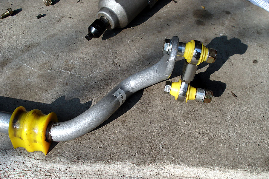
| Set the end links to be the same length as the stock end links, then install following the manufacturer instructions (in particular, make sure the seals are up against the spherical bearings followed by a washer) |
|
 |
|
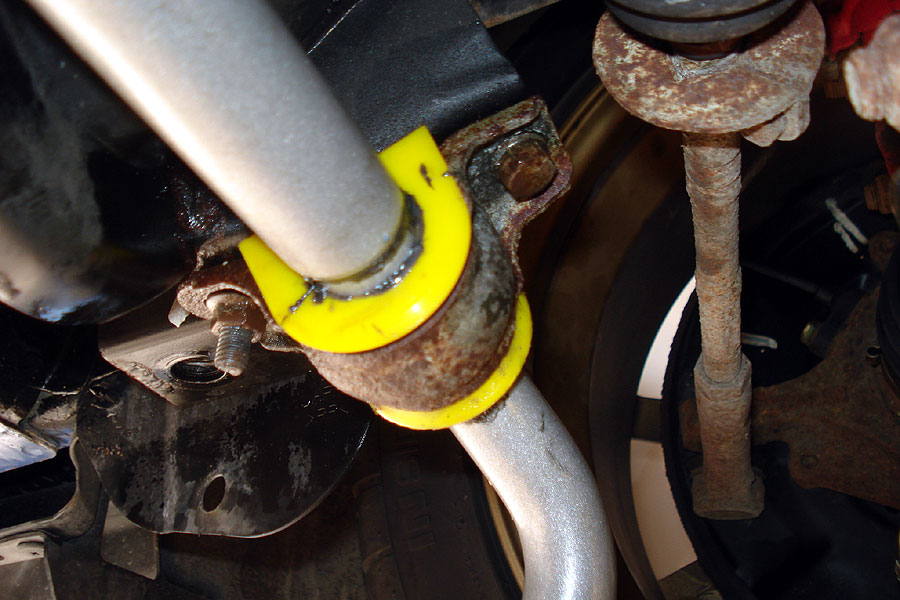
| Using the stock mounting bracket and bolts, install the new sway bar. Do not fully tighten until the end links have been connected. |
|
 |
|
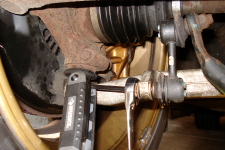
Connect the end links to the control arm and tighten.
Note: This picture is incorrect. Turns out I didn't turn the sway bar up enough, the end of the sway bar should be above the control arm, not below. This picture was taken before I discovered this problem. See below. Will take new pics next week. |
|
 |
|
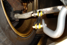
Optional: You will notice that the bar is narrower near the end links and thicker in between. Some people have had their sway bars walk (shift back and forth left and right) as a result of this.
To fix this, use a scrap of rubber hose (I used a leftover steering rack bushing) and clamp it down with a 1-1/4" hose clamp to fill the gap between the bracket and the thick part of the bar. |
|
 |
|
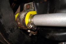
Here it is fully installed. Give it a test drive and after 100 miles check the bolts again.
Note: This picture is incorrect. Turns out I didn't turn the sway bar up enough, the end of the sway bar should be above the control arm, not below. This picture was taken before I discovered this problem. See below. Will take new pics next week. |
|
 |
|
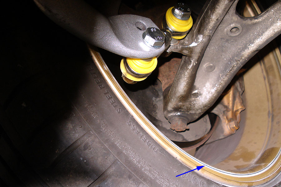
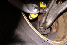
Here is a close-up of my clearance problem. I discovered this when making a u-turn when I heard a funny rubbing/grinding sound during a full-lock left turn. I had no problems turning right.
The tip of the end-link bolt rubbed against my wheel (arrow). |
|
 |
|
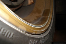
Here's a close up of the damage. The end-link bolt scratched off a ton of paint and gouged a small groove into my BBS wheels and it's my own damn fault for not comparing to the stock sway bar. :(
FAIL.
But otherwise the sway bar feels pretty good so far and the car turns much flatter.
|
|
 |
|
| |
|
|